Ham Radio 40/20/15/10 End Fed Antenna
This post is about how to build a 40/20/15/10 end fed half wave (EFHW) Antenna. One's that is working will add an 80 meter Coil to the 40M element to extend it to include the 80 meter band.
Will build the 1:64 Unun (transformer) and the 80M loading coil.
Table of Contents
1. Part List
2. Prototype
3. Notes
4. Conclusion
5. Reference Links
Part List:
1. AWG 14 Gauge Wire (100 feet)
2. Two # 18 - 20 enameled wire (4 feet)
3. FT240-43 core (1)
4. SO-239 Female (1)
5. Plastic box (1)
6. Eye bolts (2) with (4) nuts
7. Misc screws/washers/nuts
80m loading coil (110uh light weight core)
1. # 22 enameled wire
2. Thin wall white sink drain pipe 1.48 – 1.50in diameter
3. Two small screws
4. Two #8-32 brass screws
5. Two #8-32 brass nuts
6. Two #8-32 brass washers
Prototype:
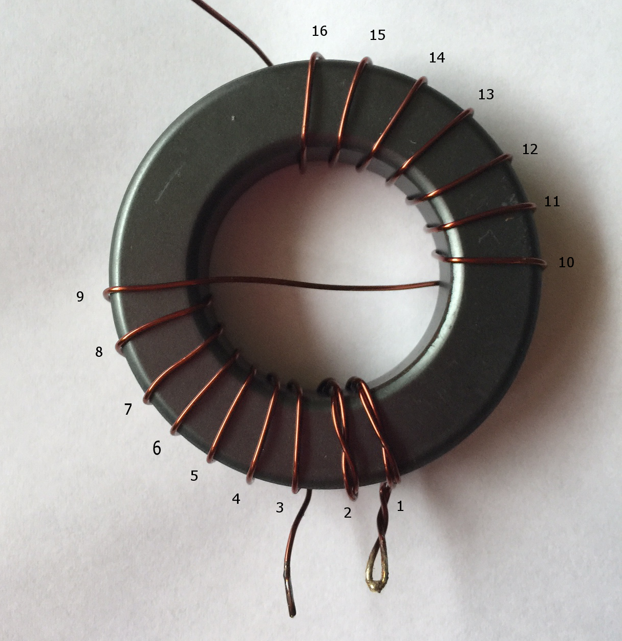
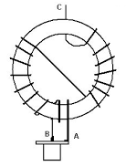
1. Let's build the 1:64 Unun (transformer) with 16 primary turns and 2 secondary turns (the 2-turn secondary winding is bifilar-twisted).
(See Reference Links: PD7MAA End-Fed Antenna)
1:64 Unun (transformer) installed in the box.
Testing the 1:64 Unun (transformer):
- Connected a 3000 ohm resistor across the ground an the input.
- Connected the MFJ-269 antenna analyzer to the SO-239
- (80) 3.500-4.000 SWR=1.6 Rs=41 Xs=21
- (40) 7.000-7.300 SWR=1.4 Rs=45 Xs=17
- (20) 14.000-14.350 SWR=1.4 Rs=45 Xs=17
- (15) 21.000-21.450 SWR=3.3 Rs=68 Xs=0
- (10) 28.000-29.7000 SWR=5.6 Rs=173 Xs=0
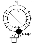
15-10 meter way off but, might improve when a capacitor is installed between the SO-239 ground / inner connector.
80-40-20 looked pretty good.
Will see where the antenna resonates on the mini VNA antenna analyzer.
Note: A 3200 ohm resistor between the ANT input / ground should indicated Rs=50.
Note: A 3000 ohm resistor between the ANT input / ground should indicated Rs=46-47
Note: 80-40-20 were close to an Rs=41-45.
Notes
Winding 1:64 Unun (transformer) on the FT240-43 core.
1. Cut a 4 foot length of AWG #18 enameled wire.
2. (A t0 B) Fold over 6 to 8 inches and twist it together.
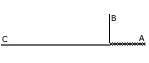
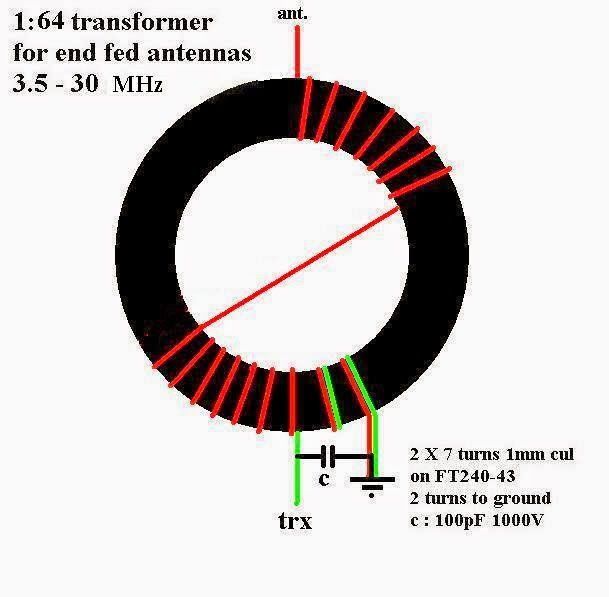
3. Start winding the Unun (transformer), each pass through the center of the core equals one turn. First 2 turns twisted section, Then 7 turns, Then cross over to the opposite side another 7 turns. Started winding the core at the ground side of the coil (A) .
Note: After installing the Unun (transformer) in the box only had 51/2 inches of wire left.
Note: For 15-10m (A ceramic capacitor of 100-150 pF is placed across the secondary side of the Matching Transformer. Its purpose is to counteract the relatively high inductance of the transformer on the 15-10 mtr bands. The capacitor should have a rating of 500-1000 volt.)
4. Now the antenna wire: Will build a 40 meter version 20.4 meters (66′ 11-1/8″) of wire, full bandwidth on 40m and some gain on 20 and 10. A Full Size dipole for 7.1 MHz would require 67′ 10-15/16″ (20.699m).
Note: Cute a 70′ (21.336m) piece of 14 gauge stranded wire, stung the end-fed up about 5-6 feet, checked SWR low on 40m around 6.3 MHz . I new that would be the case because the wire was longer than required for 7.1 MHz.
Note: After some trimming (don’t cut the wire just fold it over the twist it together) the wire length on 40m 65′ 4″.
On the MFJ-269 Antenna Analyzer
- (40m) SWR=1.1 Rs=50 Xs=8 @ 7.131 MHz (Very good)
- (20m) SWR=1.3 Rs=46 Xs=14 @ 14.160 (Not bad)
- (15-10m) way out but, that was expected without a capacitor across the SO-239 ground / inner connector.
Note: All above measurement were made without a counterpoises. Then inserted 6 ferrite beads 6″ below the 1:64 Unun (transformer), all measurement were the same. Ferrite beads were not effective choke.
Note: Raise the end-fed antenna up to 20′ hear the results:
- (40m) SWR=1.7 RS=50 XS=21 @ 7.0613 MHz
- (20m) SWR=1.7 RS=50 XS=20 @ 14.058
Readings were the same with or without ferrite beads. Started to rain so did not get a chance to add counterpoise. From what I noticed on next note will try 16′ counterpoise. Have a feeling that the ferrite beads did not have any chocking effect.
Note: Brought the end-fed antenna back down to 5-6 feet up, discovered to get a 1:1 SWR at Rs=50 I had to move the coax choke out 16-17 feet. Will experiment more when weather clears-up.
Note: Well Installed a 16′ 53/4″ counterpoise, 1/8 wave on 40m, moved the coax choke right under the 1:64 Unun (transformer), checked SWR with antenna analyzer SWR=1.1 @ 7.100 MHz and @ 7.300 SWR=2.0 at 100W.
Note: Will add 110uH coil for 80m when, I install the antenna at the cabin, thinking that it might take an additional 8′ of #14 wire for 80m. Will see…
Note: After trimming the 80m section it only took 5′ 7″ after the 80m coil.
Thehe 80m loading coil:
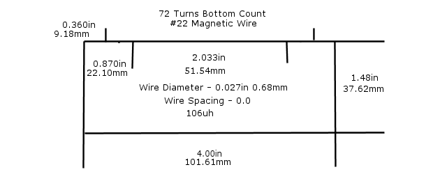
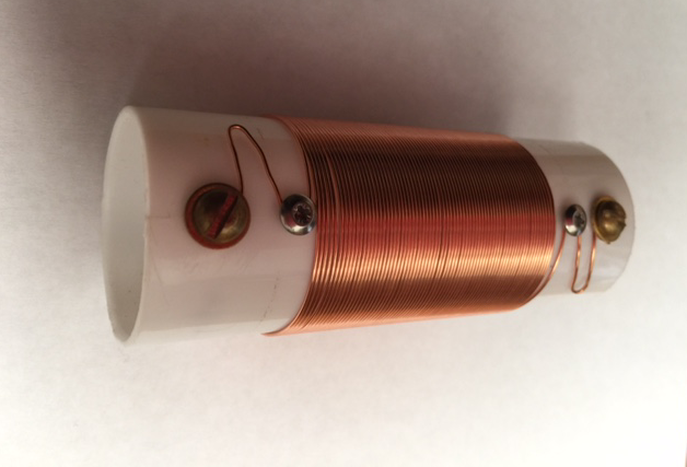
Note: The thin wall PVC core (very light weight coil). The calculated coil 108uh the measured 101uh. Used a 7 feet piece of AWG #14 wire for the 80m section, then tuned to final length.
(See Reference Links: PD7MAA End-Fed Antenna) for 80-40-20-15-10 meter long wire
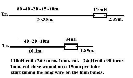
Note: It is recommend installing a choke not right at the Unun (transformer), but at 2-3 mtr (6-10 ft - 0.05 λ) and 11 mtrs (36 ft) from the Unun (transformer). Making the coax radiate will work, but is often undesirable. A simple and better solution is to use a piece of wire at the opposite end of the transformer winding to which the radiator is connected. A short wire is all that is needed: about 0.05 λ - 2.2 m or 7 ft for the 80m end-fed. (See Reference Links: Multi-band End-Fed Antenna)
Replaced the 40m 20.35m wire with a 80m 40.7m wire had wider band width on 80m, but notice no better performance than 40m 20.35m wire. So now back to 40m 20.35m with 80m coil.
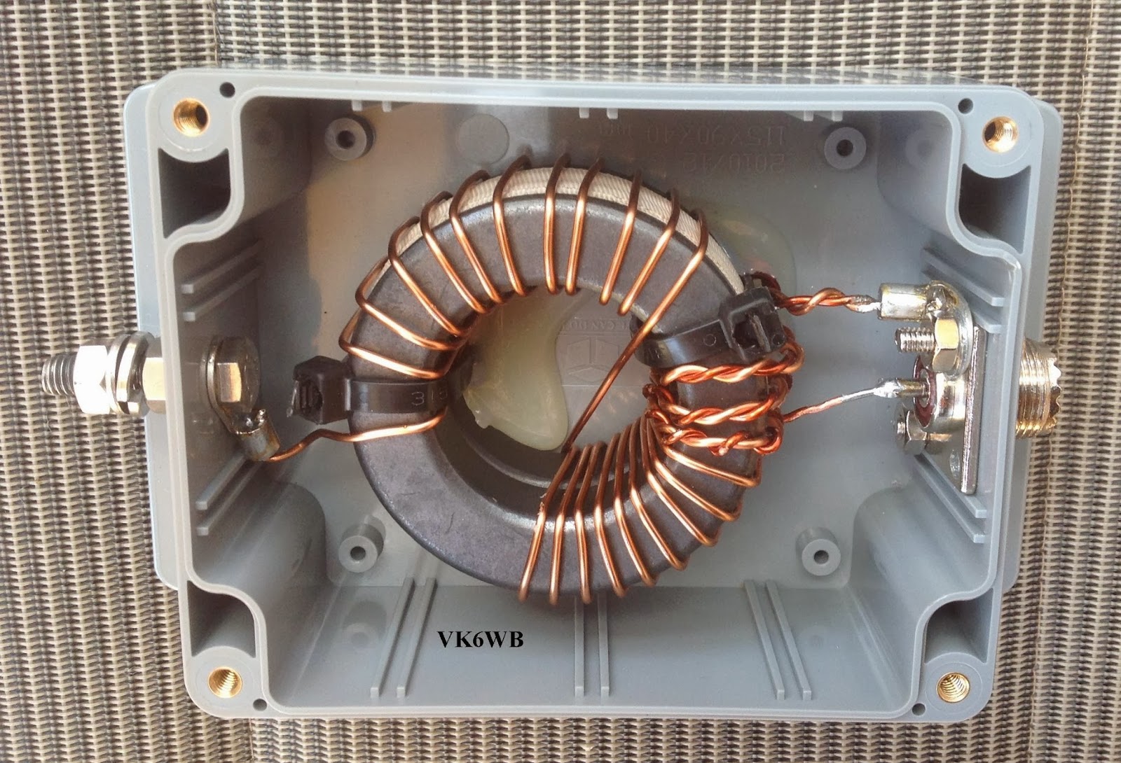
High power end-fed for 80-40
Stack 2 FT240-43 cores and add 3 primary and 21 secondary winding’s with 1.5mm enameled wire to form a 500 Watt key down transformer.
Here is the well build Unun (transformer) optimized for 80-40m. by Gus, VK6WB . You can clearly see the 2 cores for high power use.
Another high power matching network: Two FT240-43, wind 2 turns twisted, Then 5 turns, Then cross over opposite side 7 turns.
Reminder:
FullWave
FW = 984 / frequency = feet
FW = frequency feet * 12 = Inches
FW = frequency feet * 0.3048 = Meter
Dipole FullWave
FW = 468 / frequency = feet
FW = frequency feet * 12 = Inches
FW = frequency feet * 0.3048 = Meter
1/4 (.25) = FW * .25
1/2 (.60) = FW * .50
5/8 (.625) = FW * .625
(.64) = FW * .64
As the antenna goes up in height (The center Frequency will go down).
Example: Antenna Center freq at 6′ 7.131 MHz Raised Antenna to 20′ 7.0613 MHz
Conclusion
The End-fed antenna with a 1:64 Unun (transformer) is well worth building. Although about 1S units down from my 20-40-80 fan dipole center up at 30′, with one pre-amp on the end-fed 5-6 feet up matched the fan dipole. Very nice quiet receive antenna with pre-amp off.
Some Transceiver SWR measurements up 12′ with 10w power:
Note: With a 16’7″ AWG #14 counter-pose.
7.100 – 1.5
7.150 – 1.25
7.200 to 7.300 – 1.1
14.100 to 14.200 – 1.1
14.250 to 14.300 – 1.2
14.350 – 1.5
3.700 – 1.8
3.720 – 1.5
3.750 to 38.00 1.1
3.900 – 2.0
The 80m section after the coil 5′ 7″.
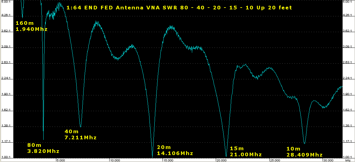
Antenna Scanned With Mini VNA NO counter-pose: