
LinkSprite R4 Relay Board Antenna Rotator Web Controlled
Attention!
This project is (obsolete) due to the LinkSprite R4 Relay Board being unavailable.
There will be a new project posted using a available ESP8266-12 based relay controller.
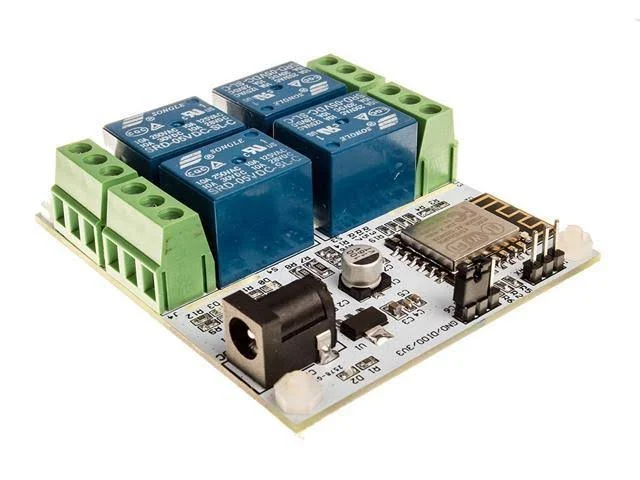
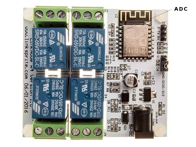
This post is about how to remote control a amateur ham radio antenna rotator with a LinkSprite R4 Relay board - ESP8266-12F WiFi module. There are many 4 channel WiFi relay boards available on the Internet make sure that the one you select uses the ESP8266-12F WiFi module.
This is a project in progress...
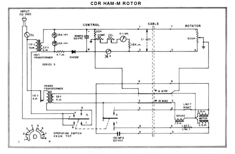
The Antenna Rotator
The amateur ham radio antenna rotator were going to try to control remotely is a old CDR HAM-M which was purchased for $ 25.00.

Programming
To program the ESP8266-12F will use the Arduino IDE 1.6.7 for Windows with ESP8266 Add-on installed.
Libraries
- ESP8266WiFi.h 1.0.0
- WebSocketsServer.h
- index.h
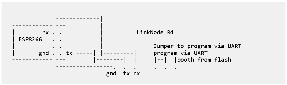
LinkNode R4 Board Setup
- Ardunio IDE 1.6.7
- Board: "Generic ESP8266 Module"
- Flash Mose: "QIO"
- Flash Size: "512K (64K SPIFFS"
- Debug Port: "Disabled"
- Debug Level: "None" "HTTP_SERVER"
- IwIP Variant: "v2 Lower Memory"
- Reset Mode: "ck"
- Crystal Frequency: "26 MHZ"
- Vtables: "Flash"
- Flash Frequency: "40MHz"
- CPU Frequency: "80 MHz"
- Builtin Led: "1"
- Upload Speed: "115200"
- Erase Flash: "All Flash Contents"
- Post: "your come port"
- Programmer: "Arduino as ISP"
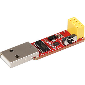
USB Programmer
This module is a USB programmer for ESP8266 modules of type ESP-01 will use this to program the ESP8266-12F on the LinkSprite R4 Relay board.
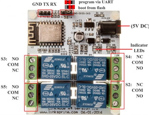
Relay Assignment
- S4 = GPIO12 LED D10 = CW
- S5 = GPIO13 LED D8 = CCW
- S3 = GPIO14 LED D4 = BRAKE & ROTOR SWITCH
- S2 = GPIO16 LED D3 = ANTENNA 1-2
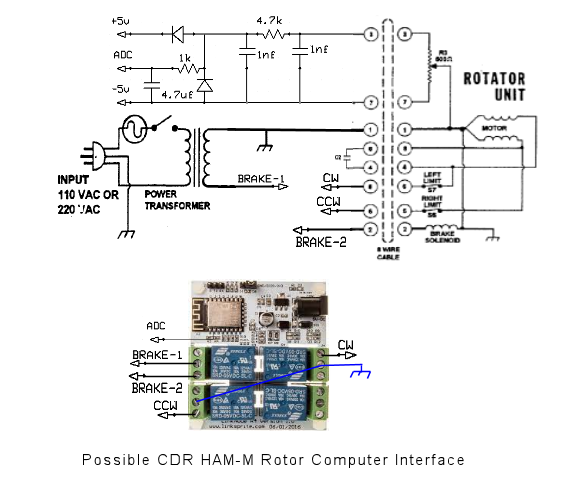
Schematic
Arduino IDE Sketch
#define rotator_analog_az A0 // reads analog azimuth voltage from rotator
// Set Relay Pins
int rotate_cw = 12; // relayS4 CW
int rotate_ccw = 13; // relayS5 CCW
int brake_az = 14; // relayS3 BRAKE & ROTOR SWITCH
int antenna = 16; // relayS2 ANTENNA 1-2
//Set relay pins to outputs
pinMode(12,OUTPUT);
pinMode(13,OUTPUT);
pinMode(14,OUTPUT);
pinMode(16,OUTPUT);
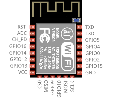
ADC Modification
The ESP8266-12F WiFi module on the LinkSprite LinkNode R4 Relay board, will need a small modification. To access the ADC (A to D converter) will have to tap a voltage divider onto pin 2. Because the ADC in ESP8266-12F is only 0-1V the voltage divider will need to be calibrated for the antenna rotator.
Schematic
Conclusion
.