
Ham Radio 40/20/15 Meter Half Wave Fan Dipole Antenna
This post is about how to build a 40/20/15 meter half-wave fan dipole antenna. Ones that is working will add a 80 meter Coil-loaded element to the end of the 40m element.
As you can see in photo below this multiband fan dipole install just like a monoband dipole.
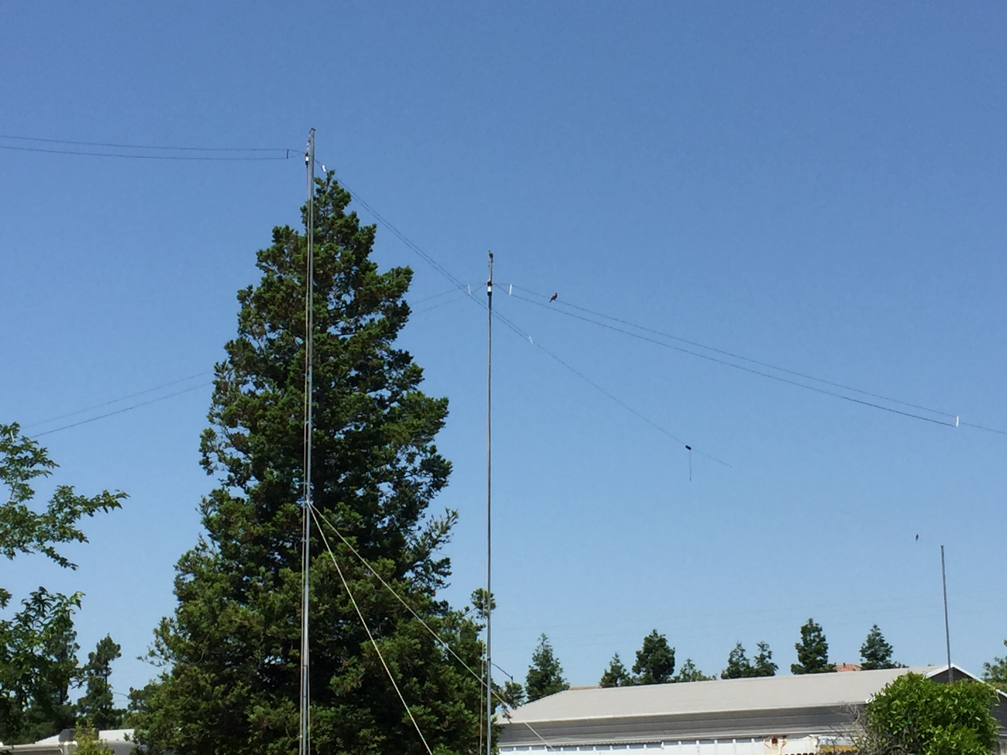
Table of Contents
1. Part List
2. Prototype
3. Notes
4. Conclusion
5. Reference Links
Part List:
1. Center Tee
2. 14 Gauge Wire
3. Two 4-1/2″ plastic Spacers
4. Two 1/2″ PVC end isolators
5. Two – 96.74uhuh Loading coils
6. One – Spool #18 Magnetic wire
7. One – 8 foot 1-1/4 underground S40 rigid PVC conduit
8. One Optional 1:1 Balun.
Prototype:
Build the 40-20-15 meter Fan Dipole
Step 1. Cut two 36′ section of #14 wire.
Step 2. Cute two 16′ section of #14 wire.
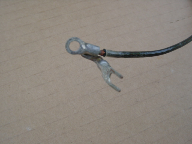
Step 3. Strip 2″ off one end of 20/40 meter #14 wire sections (Note twist the wire tight).
Step 4. Solder on the Ring/Spade terminal.>
Step 5. Attach the 20/40 meter #14 wire section to the center tee.

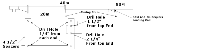
Step 7. Drill wire feed throw holes in spacer. (See Drawing)
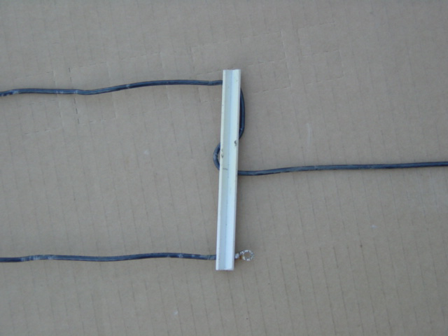
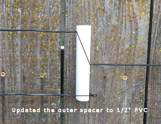
Step 9. Position inner spacer 2″ from the center Tee. (See first Antenna photo)
Note: wrap some electrical tape on each side of the spacer to keep it in place.
Step 10. Position second spacer 16′ out from the center Tee on the 20m wire.
Step 11. Solder a Ring terminal on the end of the 20m wire to keep it in place.
Closer-up view of how the 40m wire thread’s through the center spacer.
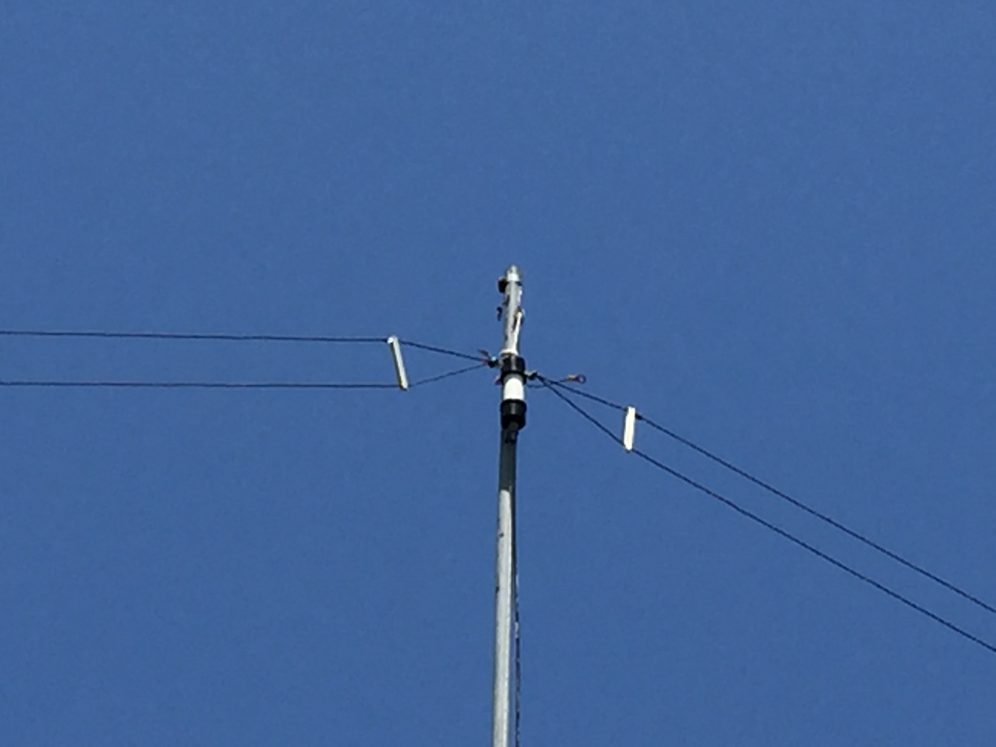
Now raise the antenna at least 20 feet off the ground and go through the normal tuning procedure using a antenna analyzer or swr meter.
Things to remember when Tuning the antenna
Add/Remove equal amount of wire from each end of the 40, 20 meter element to raise/lower the resonance frequency.
example: The 40m element is at 6.8468Mhz adding 6 inches will move it up around 7.2675Mhz, removing 6 inches will take it back to 6.8468Mhz.
Also the resonance frequency will go up when raised above the height were the antenna was tuned.
I tune my antennas to the lower end of the desired frequency, then add a tuning stub to the end of each element to fine tune the antenna. See diagram in Step 7 above.
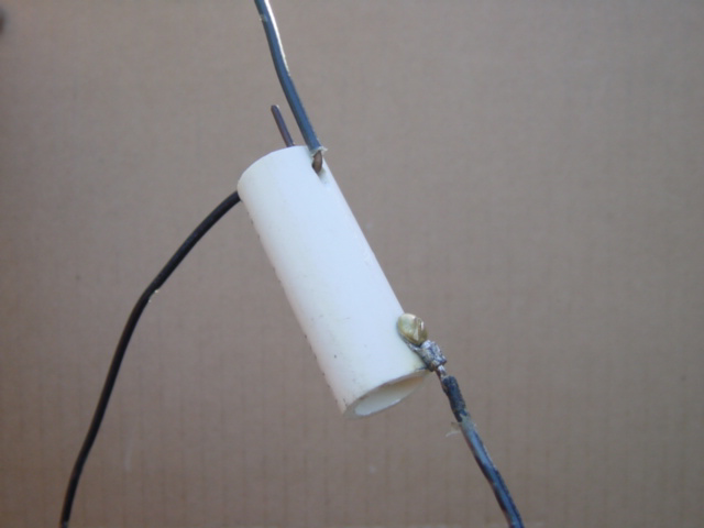
Making the 80 meter Loading Coil
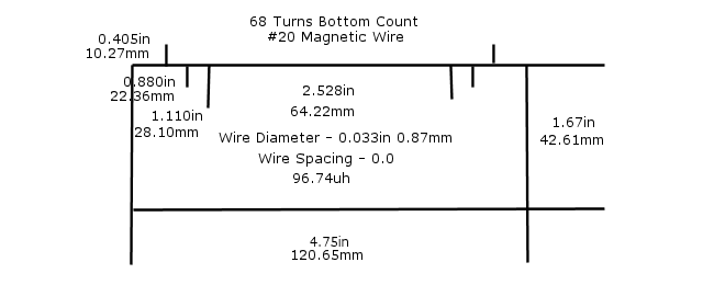
Step 2. Follow the diagram and wind 68 turn on the coil core
Step 3. Connect the 80m loading coil to each end of the 40m section
Step 4. Connect 5 feet of AWG #14 wire to the open end of each coil
Step 5. Connect a 2feet of AWG #14 wire though the 80m coil to the 40m terminal
Step 6. Tune the 40m section first then the 80m section
Note: See diagram in Step 7 / photo above. All measurements are approximates. Coil inductance should be somewhere between 96.00 – 110uh.
Remember: You might have to retune the other elements when you add the 80 meter element.
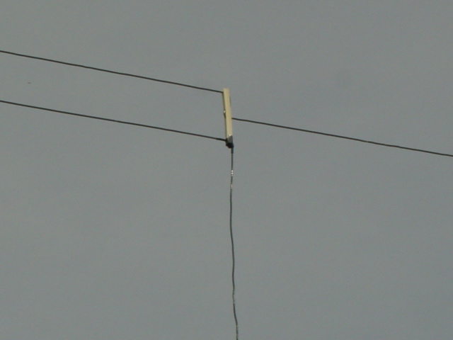
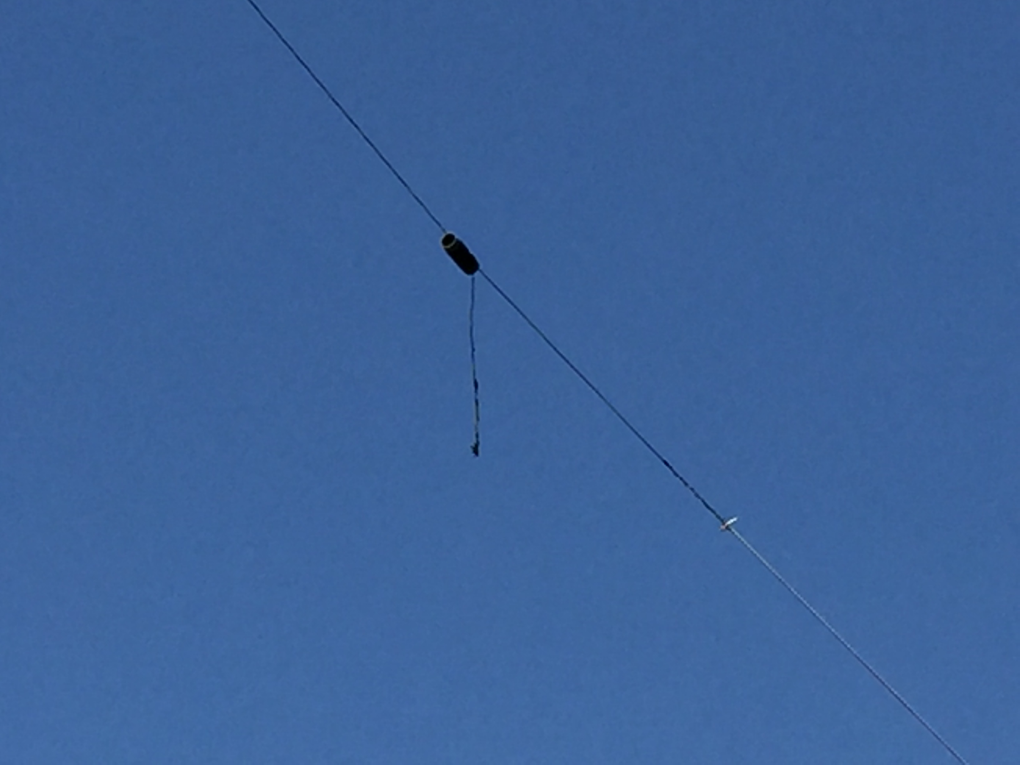
View in the air 80m loading coil with 40 meter tuning stub going though the 80 meter coil.
Notes
The Position of the middle spacer is not critical, I just positioned at the end of the 20 meter element.
At 20 feet up, the 20m antenna will tune down to a 1.0-1 swr, on 40m it won't but if the center of the antenna is raised to 30 feet the swr will be less then 1.2-1 swr on 40m.
The nice thing about this fan dipole is that the middle spacer keeps the 20m section nice and tight. The key to this is the way the 40m wire is threaded through the middle spacer.
I have been using the 80/40/20/15 meter version for many year and it has been a one of the best antennas in the air.
Originally build this antenna with a simple center T but now using a 1:1 balun as a center T the antenna is much quieter with a 1:1 balun installed.
Conclusion
This 80/40/20/15 meter fan dipole antenna works really well.
It also works on 10/17 meter with the antenna tuner.
It is my favorite multiband dipole antenna because it installs just like a monoband dipole.