
Ham Radio Remote Control Radio Interface
This post is about building a ham radio remote control radio interface to remotely operate non-CAT-controlled amateur ham radio transceivers with a Raspberry Pi and ham radio remote control software.
-
Functions:
- Turn radio power On/Off
- Toggle Push to Talk (PTT)
- User-selectable GPIO pins
- Route Speaker-Microphone Audio between the USB Audio adapter and the Radio

Prototype Circuit Development
Schematic

Click image to enlarge
Prototype Printed Circuit Board (PCB)
PCB Layout

Click image to enlarge
Working Prototype
Icom IC 2AT

IC 2AT - Ham Radio Remote Control Radio Interface - USB Audio adapter - Raspberry Pi
Notes:
This project still in the experimental stage...
-
Jumpers J1-J7 custom PTT options:
- J1-J2 Transistor IC 2ATPTT
- J2-J4 Transistor PTT
- J3-J5 Relay PTT
- jumper J3-J4 for PTT RLY 1
GPIO pins user-selectable.

Simple Ham Radio Remote Control IC 2AT Configuration:
-
Jumpers J1-J7:
- J1 - J2 installed for IC 2AT PTT
- All other jumpers open
-
GPIO # - Pin #:
- Power On/Off GPIO 23-16
- Push to Talk GPIO 24-18
- Antenna On/Off GPIO 25-22
- Ground pin 14
Keep the Raspberry Pi, Speaker - Microphone Audio grounds isolated from each other.
Note: GPIO pins are user-selectable pins assigned on the schematic and printed circuit board were just used for testing..
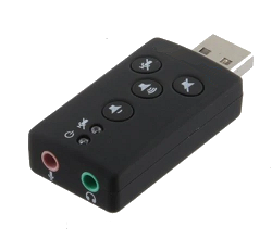
USB Audio Adapter Example
Icom - Yaesu Radio Audio Interface Example

Click image to enlarge
USB Serial to Icom CI-V Interface Example
To remote control older Icom radio you need a USB serial to Icom CI-V Interface Here ✓


Click image to enlarge
Note: To use this CI-V interface with the IC 2730, replace the 3.5mm mono plug with a 3.5mm stereo plug then connect the Tip to the Ring.
I have used this RS232 to Icom CI-V interface for many year it simple and it works, but I replaced the 2N2222 with a 2N3904.
I also use the Icom CT-17 CI-V Level Converter (no longer available from Icom)

USB Serial Adapter Example


This table shows the pin numbers with signal names and the signal direction.
| Pin | Signal | Signal Name | DTE Signal direction |
|---|---|---|---|
| 1 | DCD | Data Carrier Detect | In |
| 2 | RXD | Receive Data | In |
| 3 | TXD | Transmit Data | Out |
| 4 | DTR | Data Terminal Ready | Out |
| 5 | GND | Ground | - |
| 6 | DSR | Data Set Ready | In |
| 7 | RTS | Request to Send | Out |
| 8 | CTS | Clear to Send | In |
| 9 | RI | Ring Indicator | In |
The Icom CI-V interface is powered by pin 6 DTR by default DTR is set Low so it needs to be set High using the following command:
stty -F /dev/ttyUSB0 -hupcl
Or replacing /dev/ttyUSB0 with whatever device file actually corresponds to your USB serial port.
Note: This will have to be set every time the Raspberry Pi is turned ON.
Make sure that the Radio - Software baud rate is the same, then plug the 3.5mm mono plug into the radio CI-V port and your ready to go...
Power Module to Turn Older Radios ON/OFF Example
Older CAT capable radio without a command to turn the radio ON/OFF remotely require an external power interface.
The relay should be a High Current 12V Contactor relay to Switch DC power

Click image to enlarge
Note: this circuit can also be used for the push-to-talk (PTT) relay.
Related Links
¹ CI-V stands for Computer Interface 5 [Roman numeral "V"]
² CAT stands for Computer Aided Transceiver